RCN Windsor Build Part 5
By Dean Larson
Tag along with us for the next couple months as a pair of total amateurs tackle the complete rebuild of a Ford 302 Windsor engine. Despite being obsessive gearheads and project car addicts, neither of us have ever rebuilt a car or truck engine by ourselves before. Our subject is a bare Ford 302 engine from around 1972 that we picked up from a shop for cheap. In the end, we hope to come up with a fun and reliable Windsor engine that any guy could build at home with a few helpful resources. Will we prove to be Windsor wizards, or will this thing kick out a rod immediately? There’s only one way to find out.
Bump and Grind
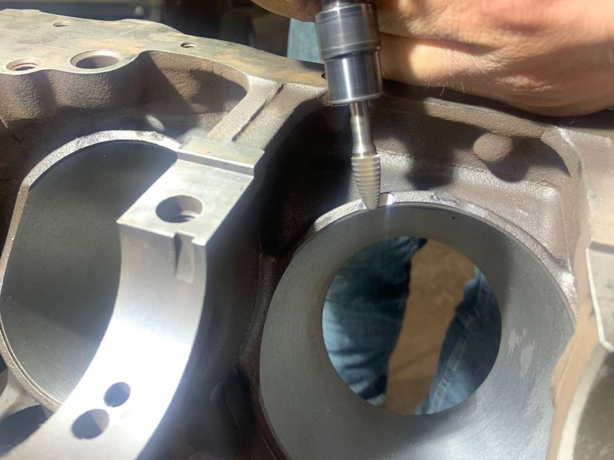
Let’s face it, up until now our Ford 347 stroker project has been pretty boring; lots of measuring, planning and a little bit of tapping — nothing too exciting. But this week it's finally time to get down to business and check off one of the most nerve-wracking parts of our build: making clearance for the stroker crankshaft. Armed with a die grinder and limited knowledge, we got to work on our unsuspecting Ford 302 block and started hacking our cylinder bores, and honestly, it was actually pretty fun!
As a quick review, recall that our new Scat 347 stroker kit for our Ford 302 block relies on a .030 overbore and a longer 3.400 stroke (up from 3.00) to bump our displacement up to 347 ci. While less than a half an inch, that increase in stroke starts to cause some problems with your stock 302 block. I suppose any part of the stroker crankshaft could cause clearance problems, but for the relatively tried-and-true 347, our only clearance problem was between the rod cap bolts and the bottom of the cylinder bore. You’ll need to address this situation before your block is ready for assembly, since you’ll be making plenty of metal shavings during the process. For us, this is the last major step before we can start assembly in earnest.
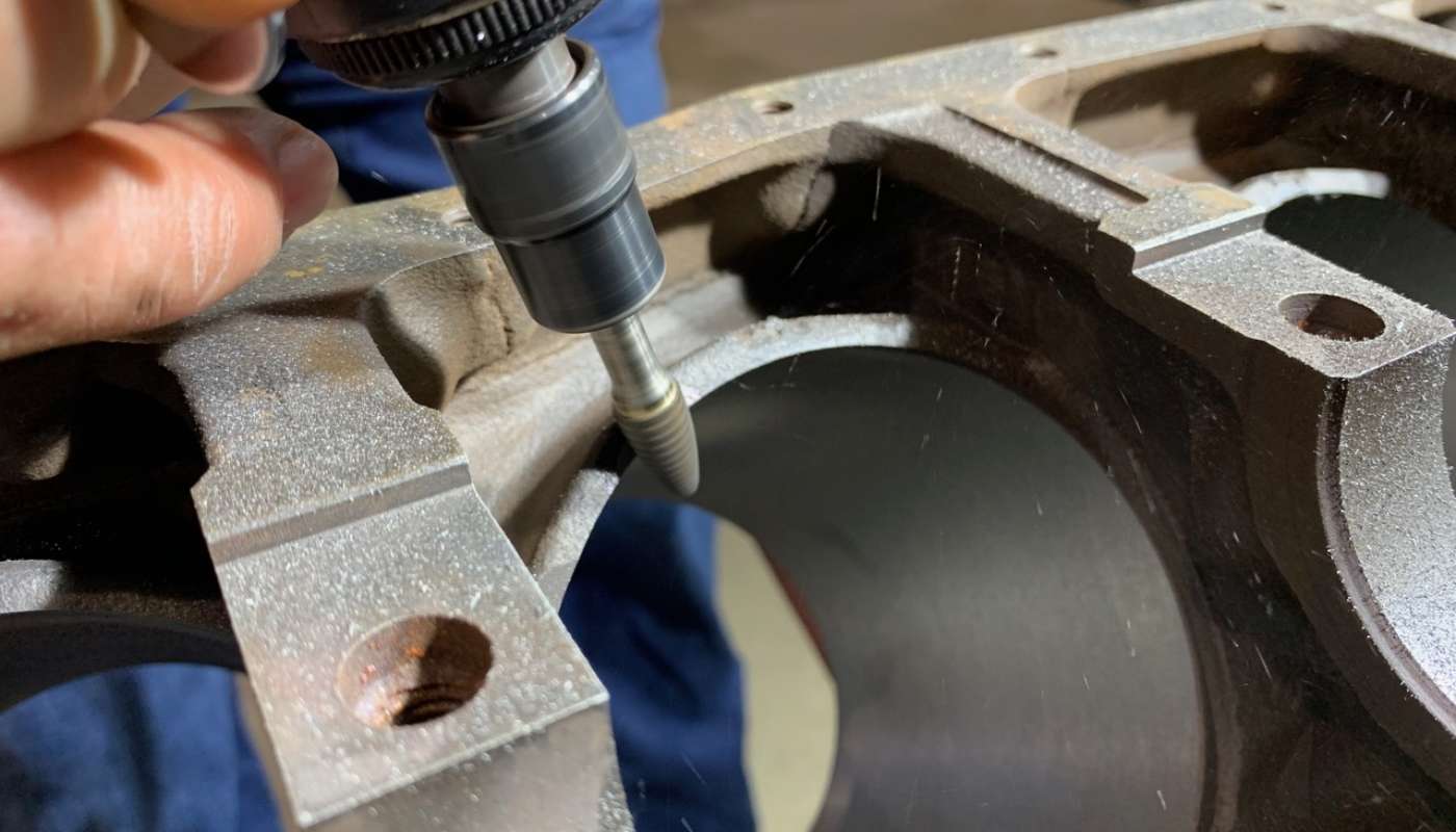
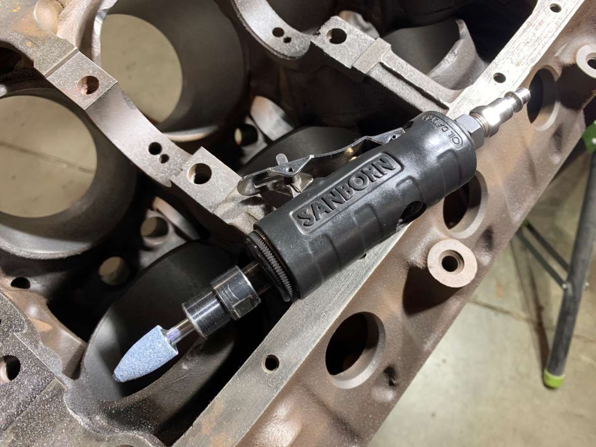
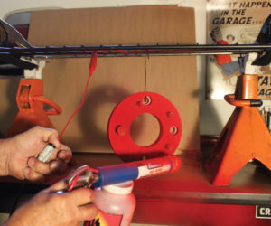
Engine blocks can differ for a whole host of reasons, but essentially, you should never assume two blocks will be identical. So instead of purchasing a pattern or anything else weird, we followed a simple process to find the clearance issues with our block using nothing more than our stroker crankshaft, one rod cap and fastener and a few of our bearings. To do the cutting, we used a cheap die grinder with a carbide rotary bit, along with a grinding stone to smooth things out afterwards.

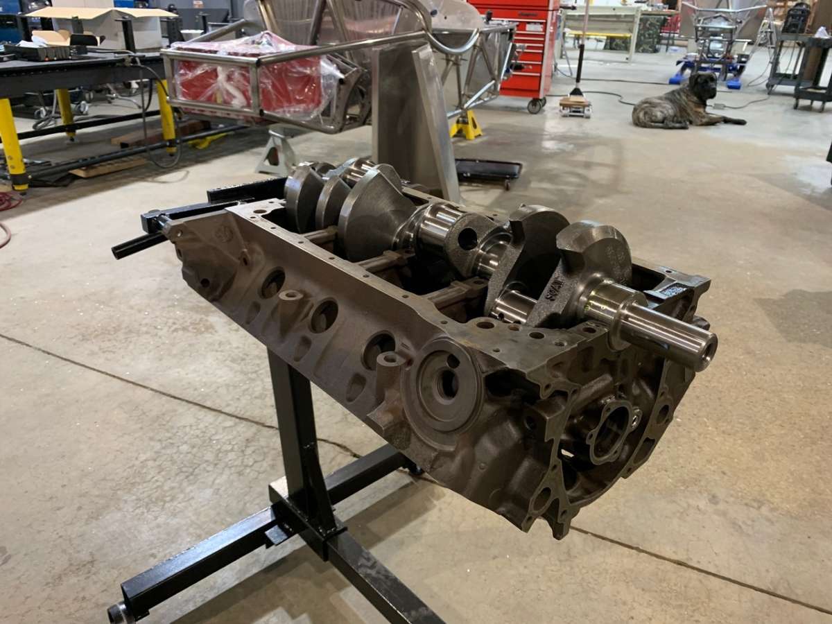
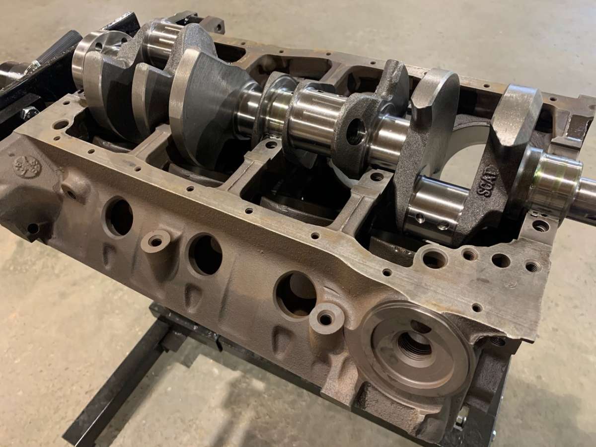

To get started, you’re going to want to make sure everything is really clean, especially your new parts and the crank journals and cylinder bores on your block. We kept a can of brake parts cleaner and compressed air on hand for the process. Next, you’ll want to snap in the upper main bearing halves in the 1, 3 and 5 locations of the block, since we won’t need all the bearings installed for this step. You’re using the upper bearing halves, and these generally have an oil groove in them, with the larger thrust bearing (controlling fore and aft movement of the crank) in the number 3 location. Since we’ll be rotating the crank for this process, we threw a bit of Lucas assembly lube on the main bearings before installing the crank. This stuff is thick as hell, and contains Zinc and Moly additives, but all we really care about is making sure our bearings and crank journals are lubed up while we’re spinning the crank.
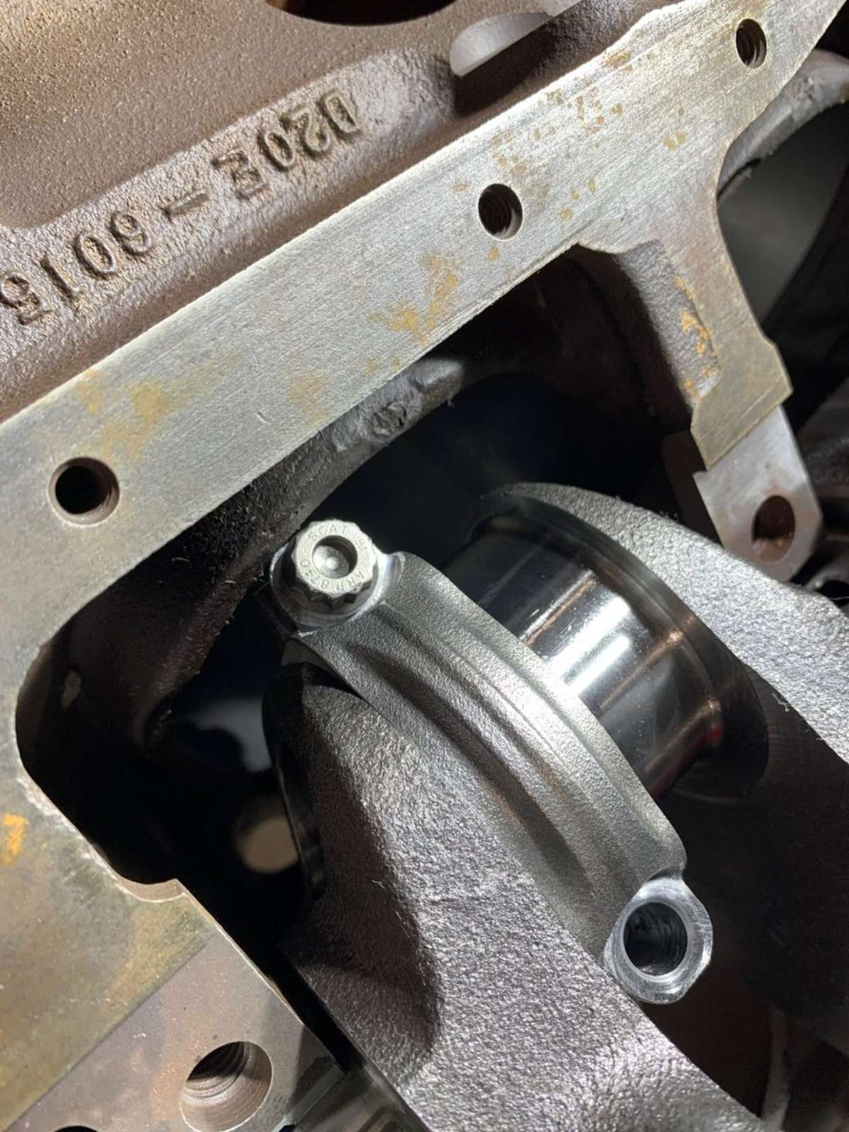
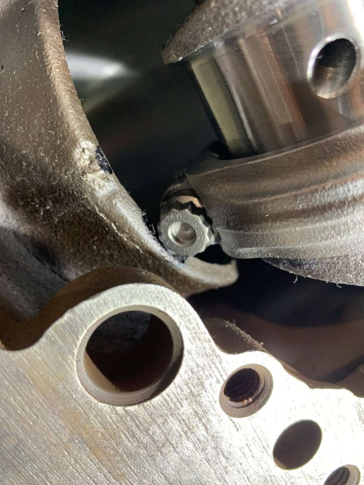
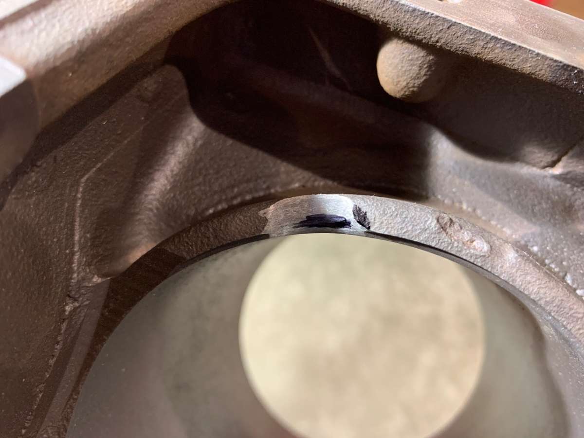
With the crank carefully installed, we took one of our rod caps and snapped one of the rod bearing halves in. We then put the rod cap on our first crank journal with a bit of assembly lube and put one of the bolts in. You’ll quickly realize that the rod bolt is where most of your interference is going to take place, and it’s probably going to happen when your crank is as close to the bore as possible. Our general process was to rotate the crank until the rod cap gets close to the cylinder bore. Stop here and then rotate the rod cap forward and backward on the crank. Repeat this process until the rod bolt starts to contact the bottom of the cylinder bore and make a mark with a paint pen (a sharpie was all we had on hand). You’ll want to check this through several degrees of crankshaft rotation, as the rod bolt will contact slightly different parts of the cylinder bore depending on the orientation of the crankshaft journal to the cylinder bore.
Throughout this process, it pays to keep a couple things in mind. First off, be sure you have the rod cap oriented correctly on the crankshaft. For us, the larger bevel on the bearing surface faced the crank webs. Also, you’ll want to keep rod angle in mind while marking these locations. When we started, we noted two separate locations on each cylinder bore that seemed like conflict areas, but then we wised up, and realized that the rod angle would not allow conflict to happen on half of these locations. When you’re confident that you’ve marked everything right, it’s time to remove the crank and main bearings and break out the die grinder.
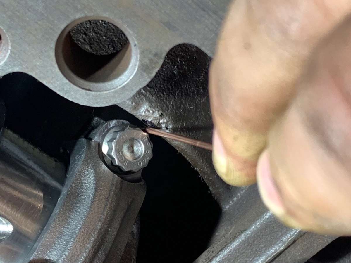
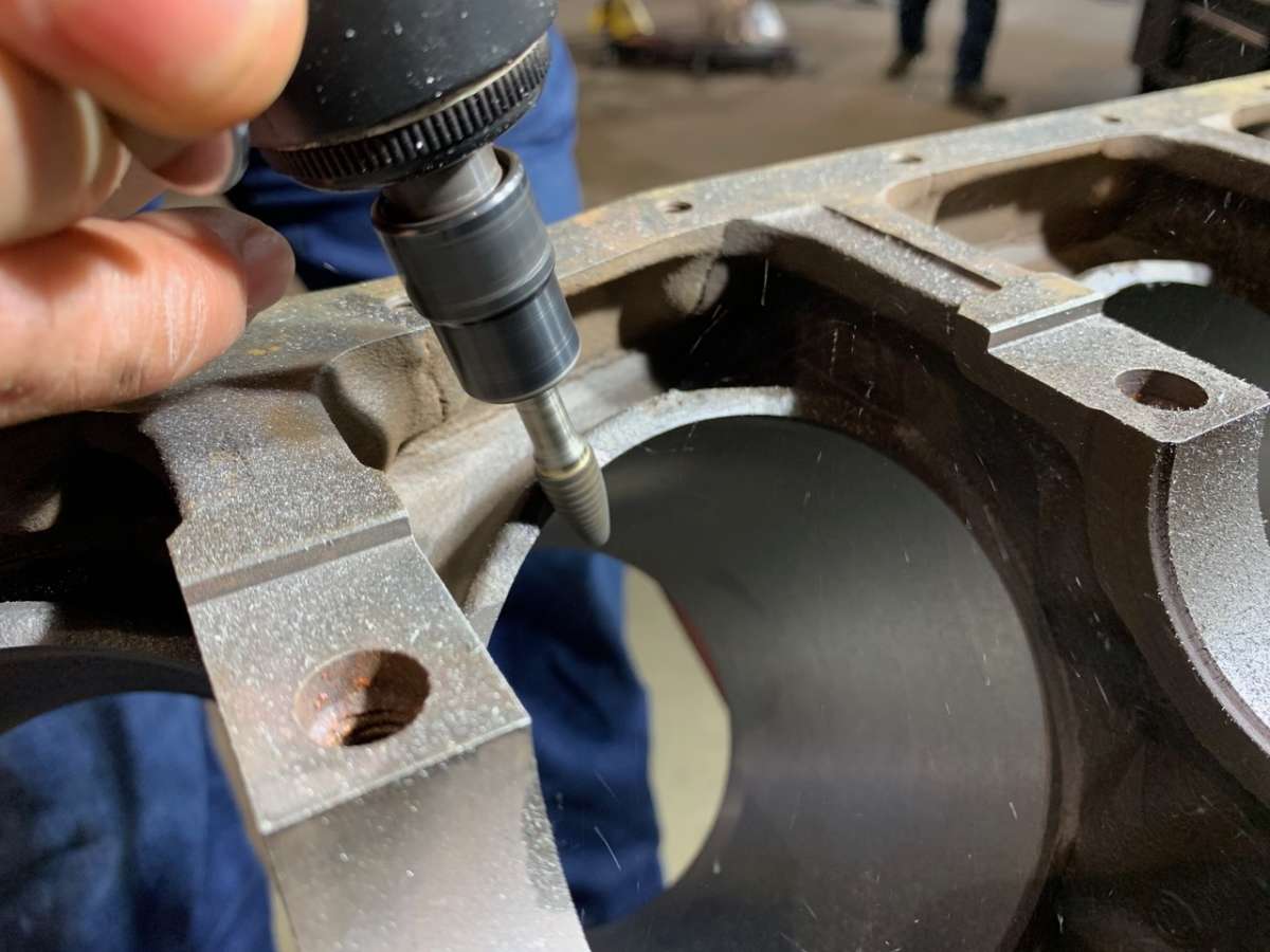
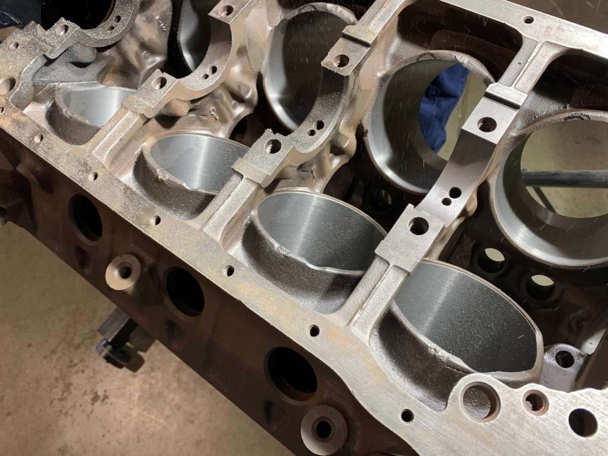
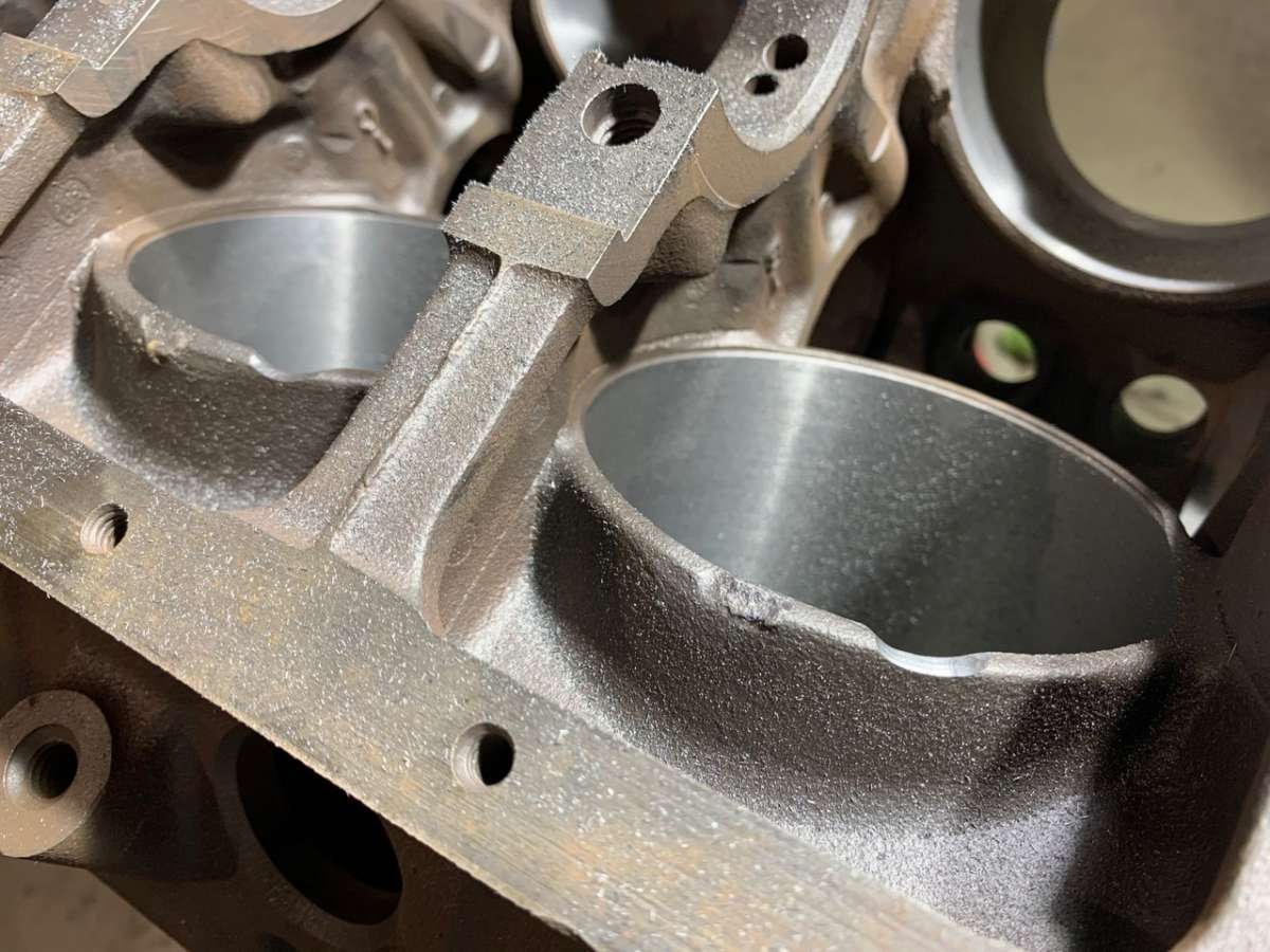
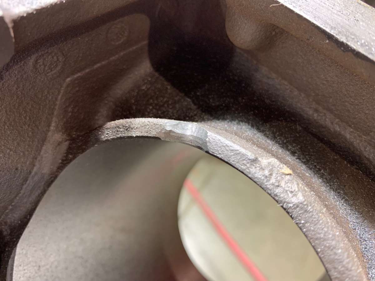
When you’re doing your homework, it pays to look at a few photos online to plan out how your cylinder notches should look when they’re done. But to contradict myself immediately, it seems like everyone does the job differently. Some blocks have a nice semi-circle cut into them while others take out an oblong oval, or even a big long window. At the end of the day, you have to remove enough material to ensure you have about .060-.080-inch clearance on your rod cap and bolt, but no more than that. It doesn’t pay to hack a big window here, just enough to make sure you clear everything. We didn’t have a feeler gauge or anything of that size, so we used a small section of ER80S-D2 TIG rod to measure our clearance. This particular rod was 1/16-inch thick, or roughly .0625 inch.
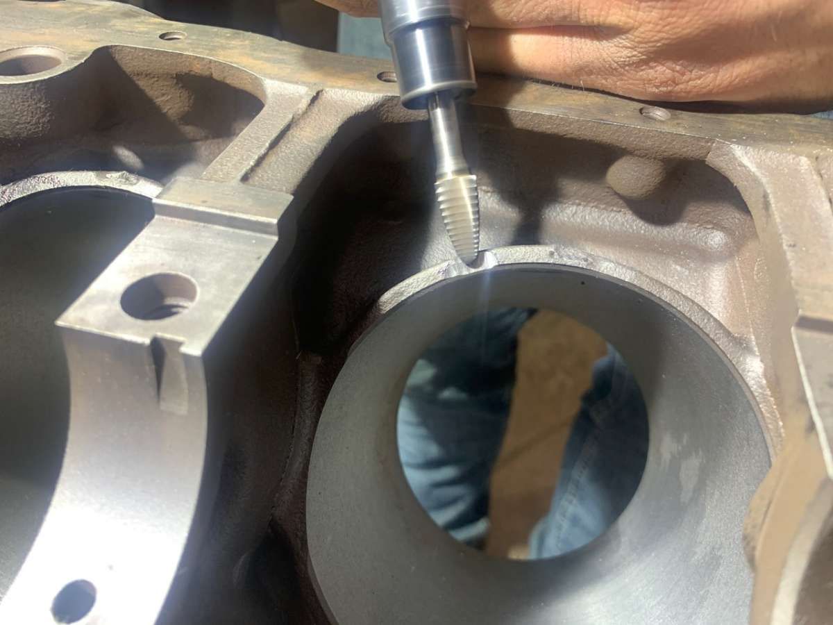
Unless you really go to town with the die grinder, you’re probably not going to take enough material out the first time, and you’ll have to repeat the process to get the clearance perfect. When you’re doing this, just be sure to get everything cleaned out perfectly before reinstalling the crank and bearings for additional test fits to ensure you don’t get a bunch of metal shavings on everything. Just go slow, be thorough and measure twice. Oh, and don’t forget the lube either!
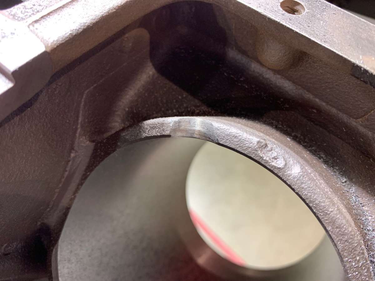
After everything clears as it should, it’s advised that you take some type of grinding stone to these areas to make sure everything is clean and uniform. You don’t want any sharp areas, and you want to have a nice smooth transition from your notch to the cylinder bore. Then hose it down again, and she’s ready for the machine shop — no sweat. Then again, it was never my block (or money) to begin with!


Comments for: RCN Windsor Build Part 5
comments powered by Disqus