Tips on Sizing your Car's Electrical System
By Dave Martin
Most of us build our rides using pre-wired fuse panels that came with our replica car, or purchased from an aftermarket supplier. The advantage of using these pre-wired units is they already take into account the circuits in the car and how many; what the typical current draw is for, say the headlight circuit; and have sized the wire and fuse accordingly. Even so, project cars tend to suffer from poor electrical systems for a number of reasons, so let’s spend a little page space on electrical basics.
Most modern cars today are based on a 12-volt DC (direct current) system where you have a battery and alternator that supply 12 volts to the car’s systems. Voltage is defined as a difference in potential between two points. If one point is the car’s chassis ground, typically at 0 volts, and the other is a 12-volt battery, you have a 12-volt system.
Placing a load, something that consumes power such as light or radio, across this 12-volt system causes current to flow through the device. This is what powers the device. Current is measured in amperes — or amps. Typically, this is as much as most people know and recognize, but it’s missing one important element: resistance.
Resistance is made up of many things in the path of the system. At a base level the device under power is the resistance, or load.
So let’s start with current. System designers are able to make calculations on how much current needs to flow for each circuit in the system, and therefore select the right wire size and fuse value using two basic formulas. These are built into the pre-wired fuse panels you can buy today, and for the most part they will work fine.
But sometimes what you connect to a circuit is not what the fuse panel-maker calculated for and intended. In that case, you need to understand what you need and make adjustments, or deal with the occasional blown fuse or intermittent operation. To do your own calculation, start with two basic formulas as shown below:
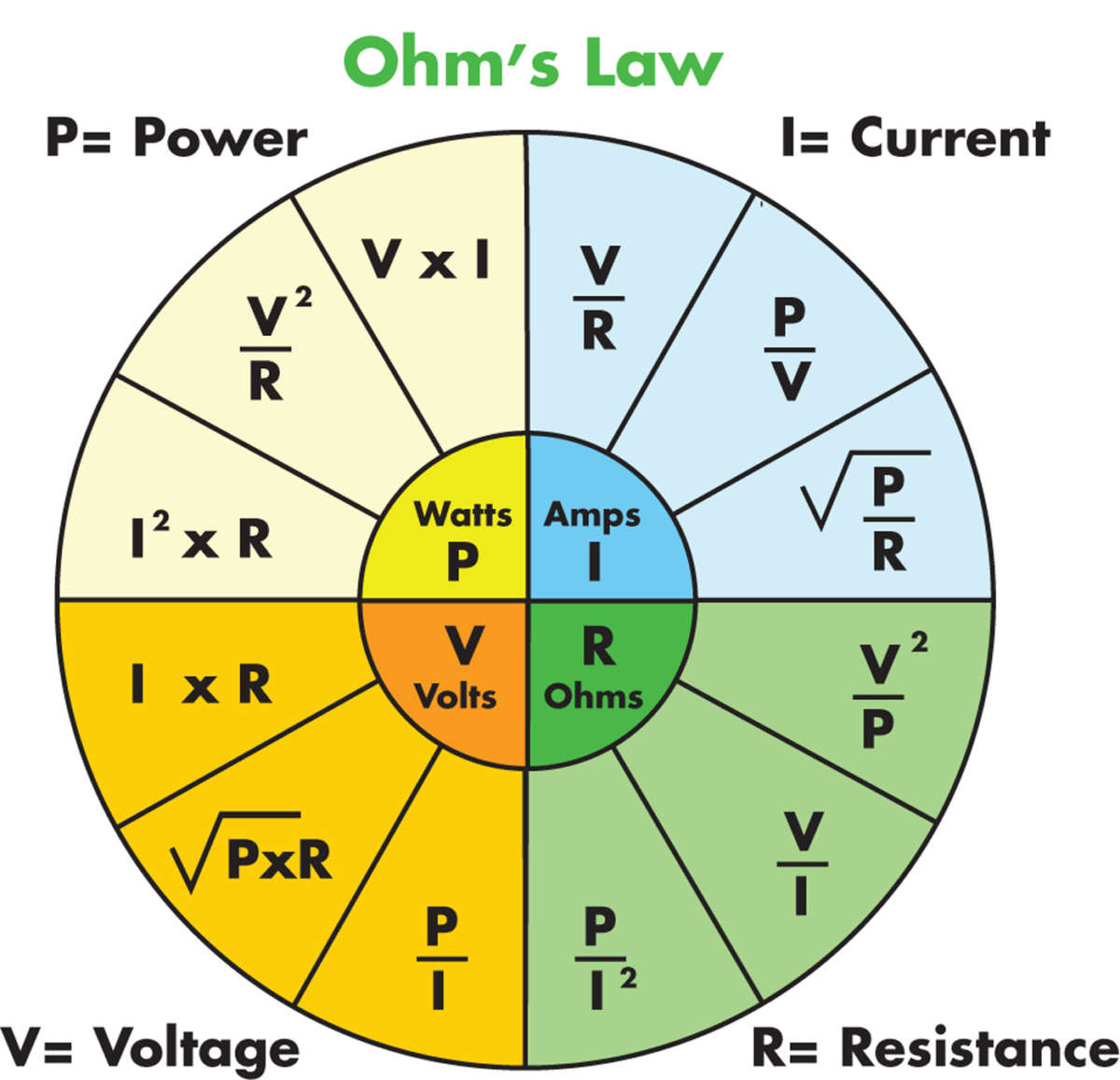
Ohm’s Law: Voltage = Current x Resistance or V=IR
Power Formula: Power = Voltage x Current or P=VI
For example, if you are calculating the current needed to handle two driving lamps rated at 55 watts each, then you could use a derivative of the power formula, since you know the power (watts) and you know the voltage. Power/voltage = current or P/V = I, so for two 55-watt driving lamps, here’s the calculation: 55 watts x 2/12 volts = 9.16 amps.
You might think that a 10-amp fuse is the right one to plug in but you’d be a little light. For fuse sizing you would select a fuse that is at least 35 to 40 percent higher than required so 9.16A x 1.35 = 12.3 to 13.3 amps. So a 12A fuse should work, but they don’t make them, so a 15A it is.
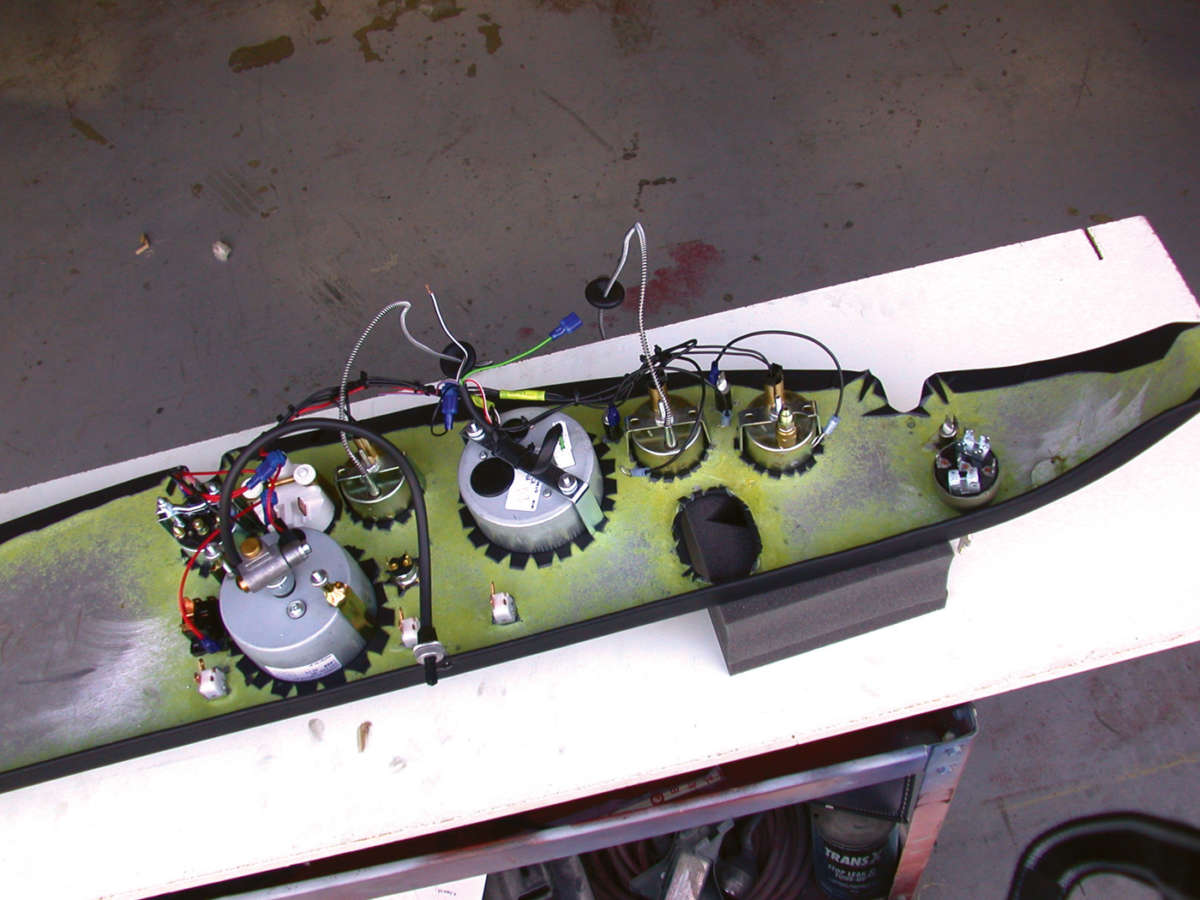
Another way is to measure the actual current in the circuit under use. This is the way I sized my system as I was building a full custom fuse panel mounted in the rear of my Daytona Coupe replica, which required doing some long wire runs, which adds resistance, and draws more current.
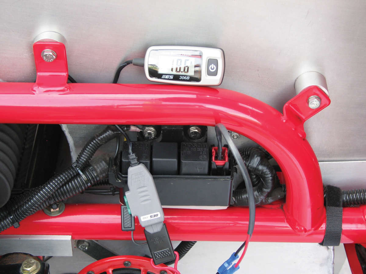
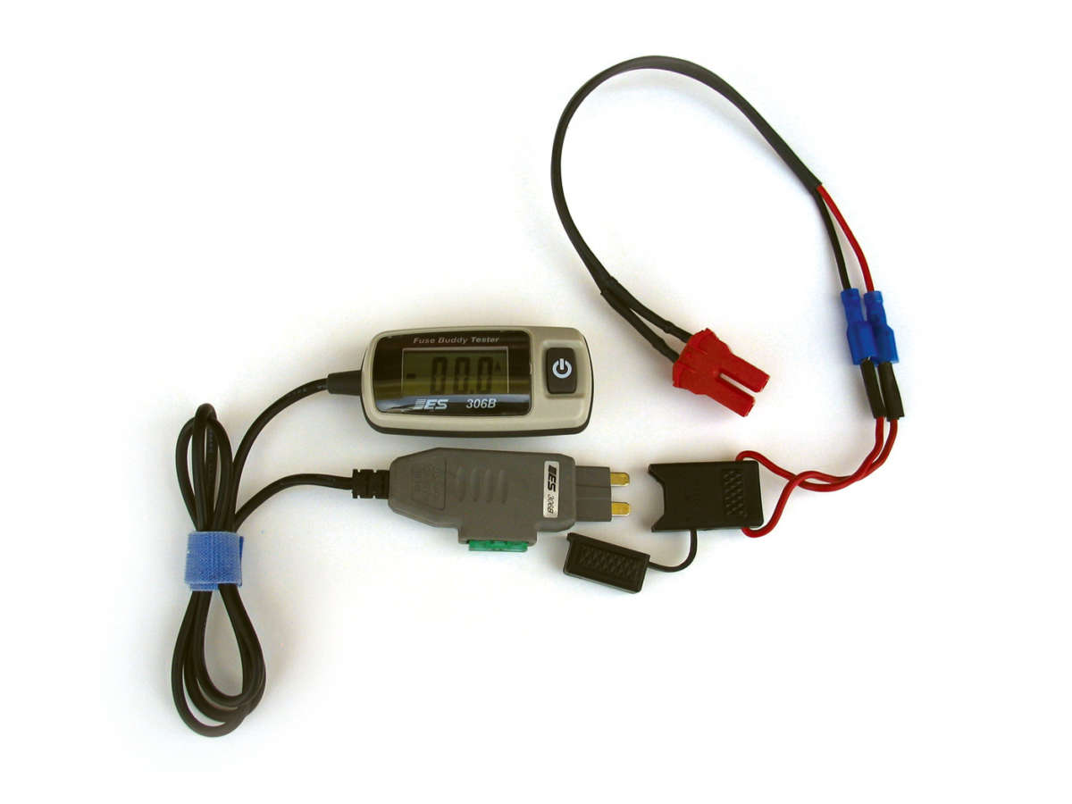
So how do you measure current in a circuit safely? A while back I bought a BES 306B Fuse Buddy Tester. This is a neat little tool that plugs into the fuse socket of the panel, and reads the current directly and safely with a clear display. You can find them on eBay for about $20, and they are worth it.

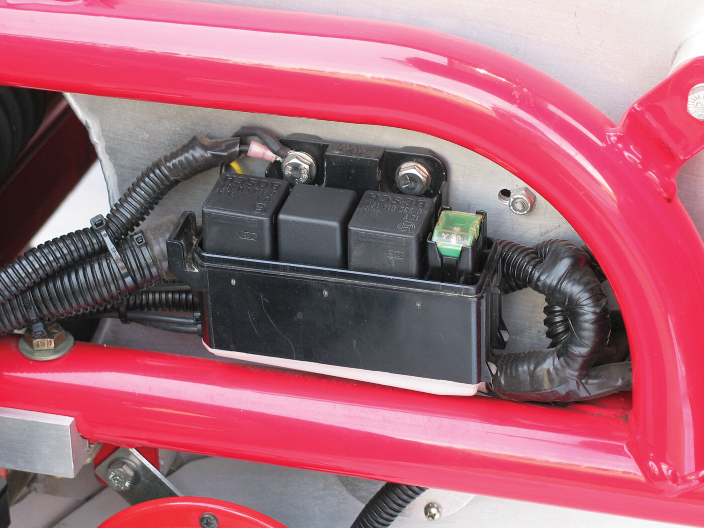
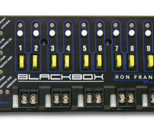
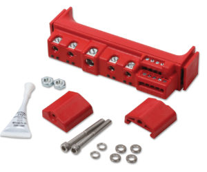
Depending on which fuse type you are using, you might need to fabricate an adapter or two on your own with parts from your local parts store. When I set up the Coupe, I mounted a bank of three relays at the front of the car to deal with the high-current applications like my fans.
The fuse holder has three relays tied to a single fuse, so I had to select a fuse that could handle all three circuits at the same time. By hooking up Fuse Buddy as shown in place of the fuse, I could switch on the different circuits and read the actual current usage. The three circuits in this relay box are: No. 1, main 16-inch cooling fan; No. 2, two 8-inch auxiliary cooling fans; and No. 3, my dual Hella horns.
With the auxiliary fans on it gave me 5.1 amps, adding the cooling fan I was reading 20.6 amps, or an additional 15.4 amps for the cooling fan. The twin horn kicks in another 12 amps for a total of about 32.6 amps. With a 35 percent margin, that gives me a calculated fuse value of 44 amps, so I can probably get by with a 40-amp.
Fans tend to have a surge when first turned on, so I’d normally go higher than 40A, but since I don’t use the horns often, and certainly not at the same time I turn on the fans, I’m good with a 40A.
All told, it’s a pretty cool tool, especially if you’re troubleshooting fuses that blow occasionally or just need to verify your fuse ratings.
Gauging matters
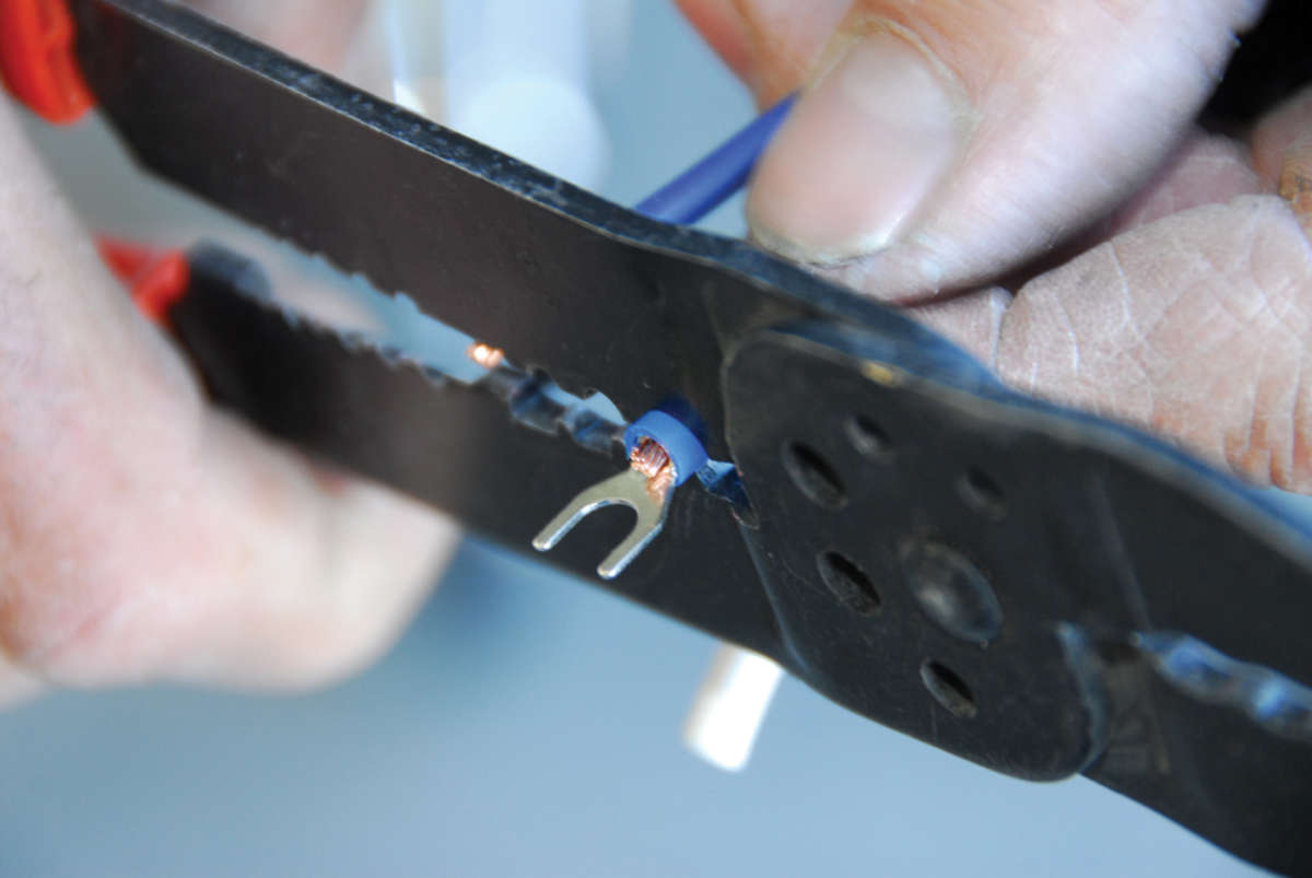
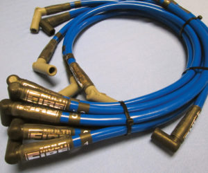
Once you know what current you’re drawing in a circuit, the next thing is to verify the wire that is going to carry the current is sized properly. The larger the wire diameter (indicated by a lower gauge), the more current it can carry.
If the wire size is too small, it starts acting like a resistor, and when you drive current through a resistive wire, heat builds up and will result in a failure. Best case is a melted wire with the worst being a short causing the fuse to blow, or even worse a fire to start in your ride.
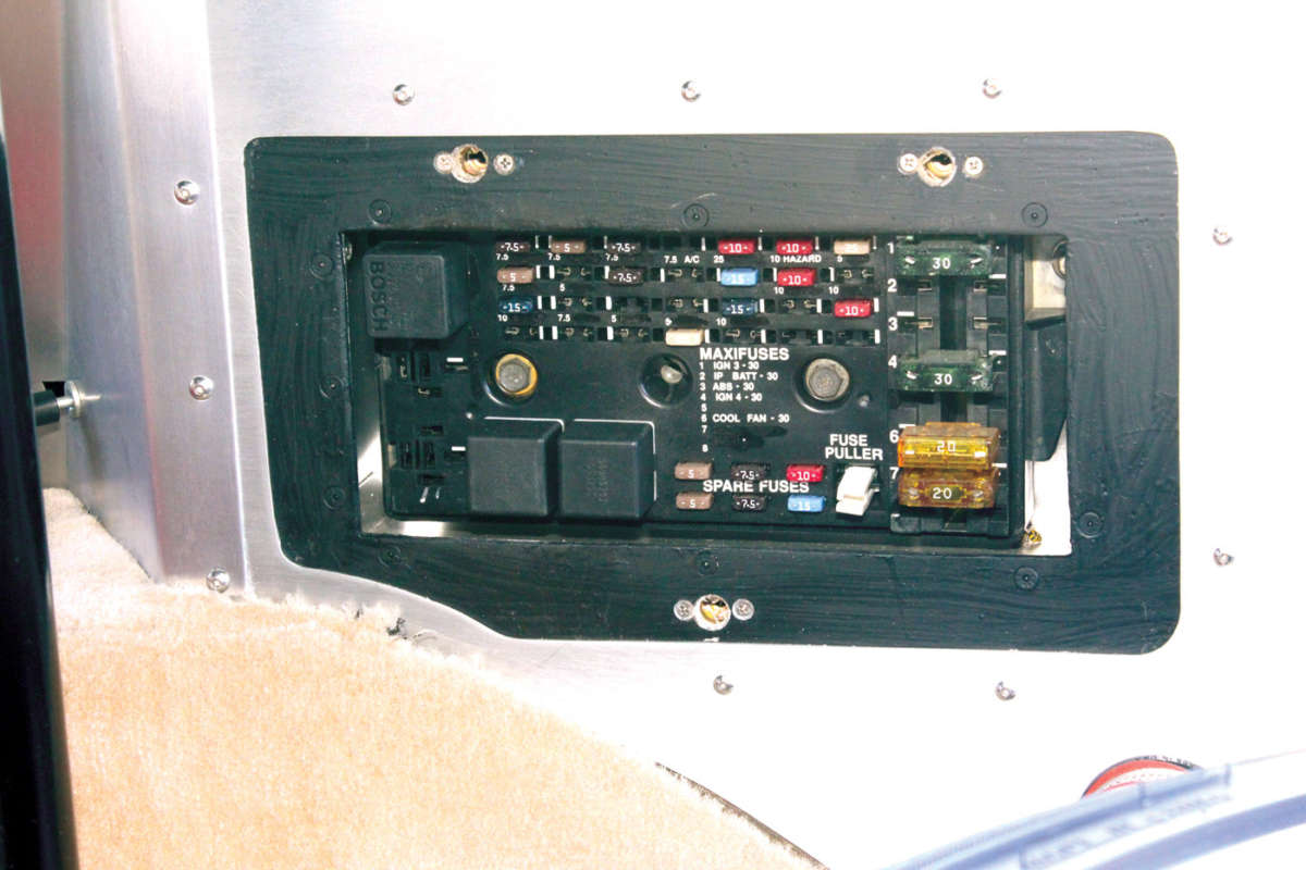
A basic rule of thumb is a 16-gauge wire can carry a maximum of 15 amps, a 14-gauge can get you to 25, and a 12-gauge to 40 amps. Most fuse panels are wired up with 14-gauge wire and a few 12- or 10-gauge for the inputs or big power draw items. Important tip: If you change a fuse to a higher value than what came with the panel, you need to verify the wire installed in the circuit will handle the new current draw. Also, allow some margin by going up in wire size (down in gauge).


Comments for: Tips on Sizing your Car's Electrical System
comments powered by Disqus