Building a Low-Tech Speedometer Calibration Device
Today’s kit cars and universal tech give homebuilders opportunities that would baffle builders of yesteryear. We have readily available component cars today with inboard coilover suspension, well-engineered chassis geometry and plenty of plug-n-play electronics to make it all work. The same can’t always be said about classic kits and replicas, and you had to get creative to make all parts from multiple donor vehicles work together.
Take our friend Lyle K. for example, who found that the speedometer on his newly purchased replica was about 17 mph off at 55 mph. With modern tech, you’d simply order up a universal speedometer calibration device like this one from Dakota Digital, and you’d be off to the races. But not so much when you’re talking about a vintage speedometer of unknown origins installed in a VW-powered Bugatti replica vehicle.
Admittedly, Lyle’s speedometer fix won’t be applicable to your modern Factory Five, Superlite or Superformance, but we can all take a little inspiration from his ingenuity and MacGyver-caliber speedometer correction device.
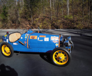
Read more about Lyle’s Bugatti Type 35B replica in the upcoming Winter 2020 issue.

As told by Lyle K.
When I bought my Bugatti kit car about 10 years ago, it had a speedometer of unknown origins and 18-inch ’32 Ford wheels on it. Therefore the speedometer read 38 mph when the car was actually going 55 mph, as determined by a hand-held GPS unit. This gave me a ratio of about 0.67 to 1.0, figures that I used to come up with the device shown in the following photos.
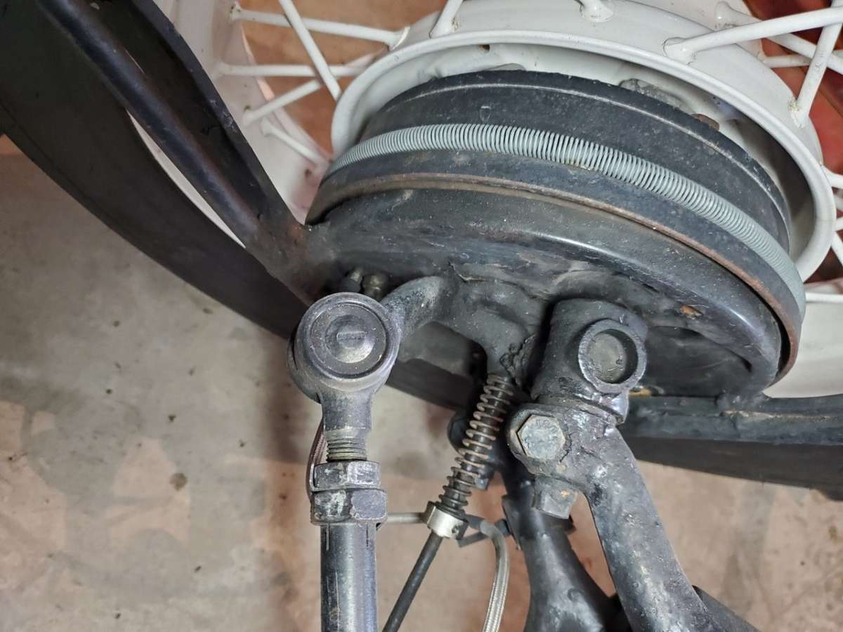
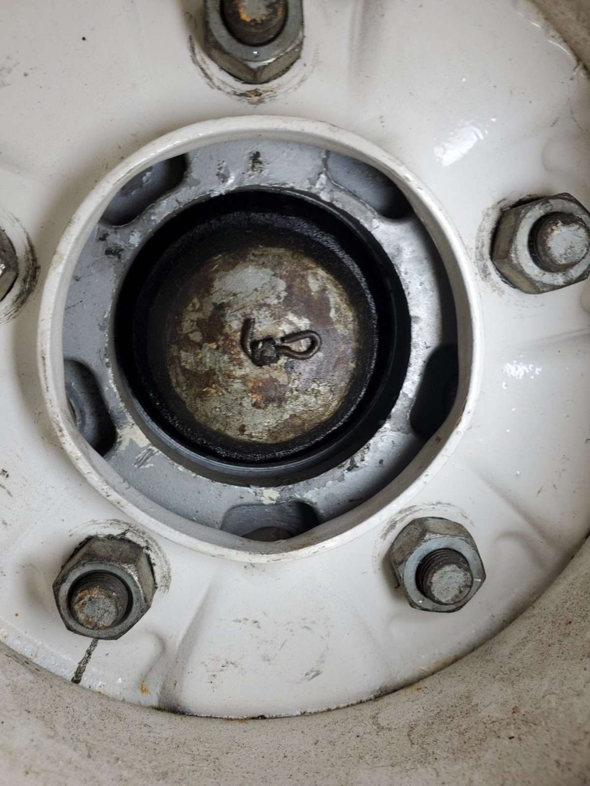
With a VW chassis forming the basis of the kit, the speedometer is driven from the left front wheel with a long cable running all the way to the dashboard. The photos show the cable entering the back plate of the wheel and coming out of the bearing cap, held with a pin through a hole through the cable.
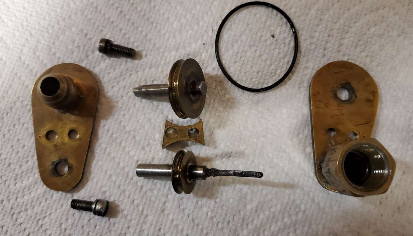
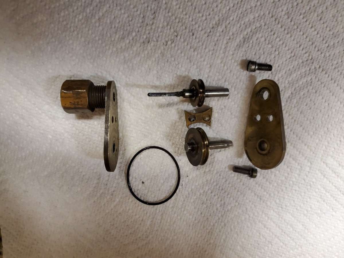
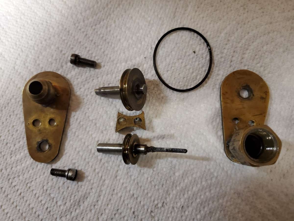
I then devised the pulley system made of brass and 0.25-inch plate. The fitting that screws onto the back of speedometer, and the one that accepts the cable from the front wheel, are brass plumbing fittings that happen to be the right size and thread pitch. The pulleys were turned on a lathe, with the big pulley measuring 1 inch, and the smaller pulley measuring 0.67 inches. The shafts are made from drill rod, and the driven shaft has a small square soldered to the shaft, and the shaft that goes into the back of the speedometer has a short piece of square speedometer cable soldered onto it.
The two brass pulleys are driven by a small rubber O-ring. It’s all very low tech, but gets the job done.


Comments for: Building a Low-Tech Speedometer Calibration Device
comments powered by Disqus