Tech Tips for Deciding on the Right Driveshaft
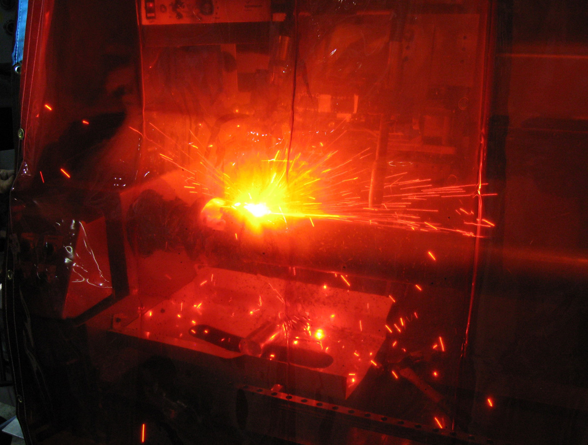
Photos courtesy of Dynotech Engineering Service and Rock West Composites
All driveshafts are created equal, right? Maybe back in the ‘70s that was the case, but not with the material and technological advances of today. Now you have choices of several different types of material depending on your application. These, combined with the endless combinations of slip yokes, U-joints and pinion yokes, means there are hundreds of combinations for a custom driveshaft. Sticking to the basics, let’s start with the tube materials—steel, aluminum, composite, and hybrid—and the variations within each.
Steel Driveshafts
Chromoly consists of steel tubing drawn drawn over mandrel (D.O.M.) with chromium and molibdium added. This top-quality steel driveshaft is usually used in very high horsepower, heavy cars.
Pros: Very high torsional strength
Cons: The most expensive of all steel driveshafts, only available in 3” diameter and is heavy.
D.O.M. 4140 is the most common racing shaft available, from circle track to drag racing, and there’s something to fit every application. As long as the shaft is sized correctly there’s no car that can overpower this shaft.
Pros: Much stronger than seam tube, relatively high critical speed.
Cons: Not many, only slightly more expensive than a seam-tube driveshaft, heavy. Steel weld yokes.
Seam Tube is the most common OEM application, perfectly suited for everyday applications, restored cars or could be carefully used in circle track and drag racing applications. Pros: The most cost-effective type of driveshaft.
Cons: The weakest of all the steel driveshafts, the lowest critical speed and heavy.
Aluminum Driveshafts
6061 T6 This is the most common OEM application for an aluminum driveshaft. Best suited for everyday applications or restoration cars, sometimes a nice alternative to the heavy steel shaft but only suited for moderate horsepower.
Pros: Light weight, never rusts and higher critical speed than steel shafts.
Cons: The weakest of all driveshafts. Remember this is the same driveshaft used on applications such as the minivans and Mustang.
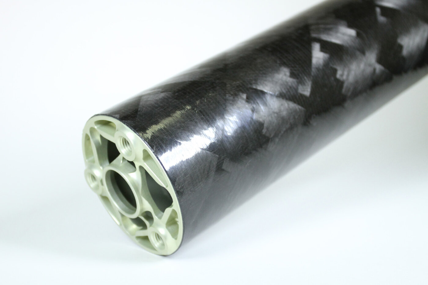
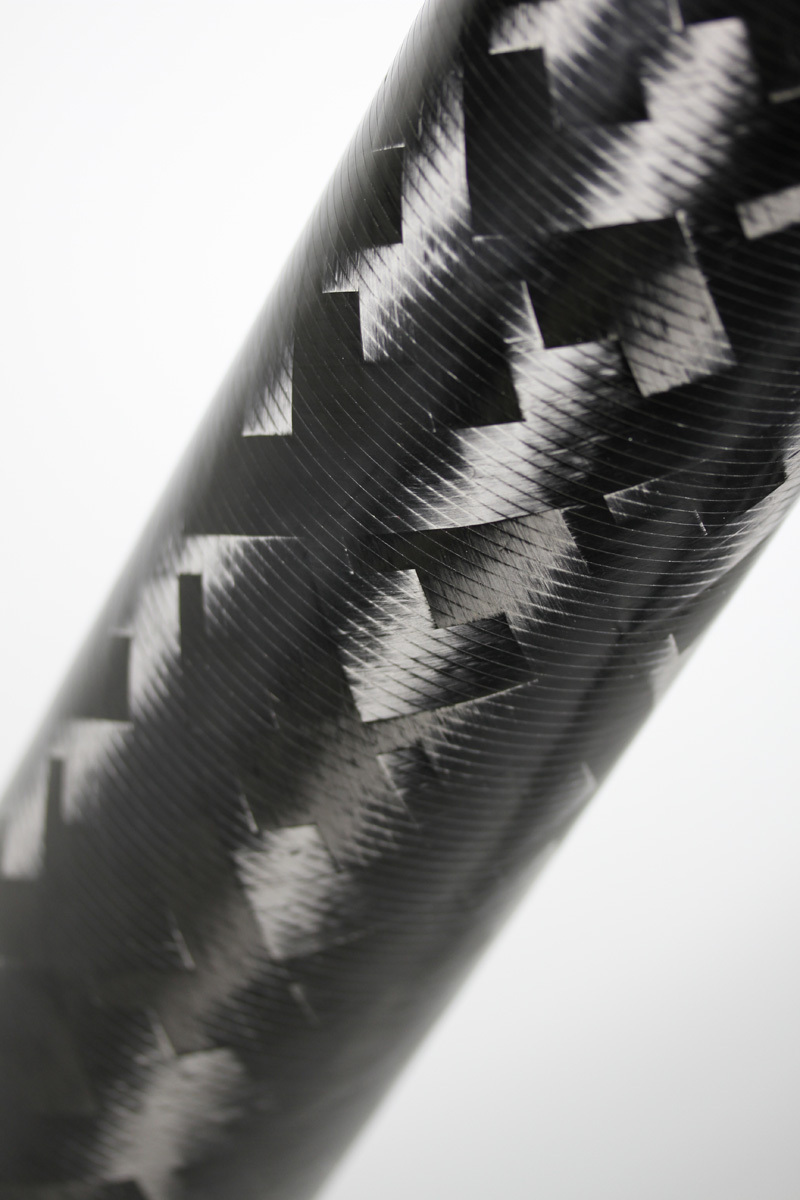
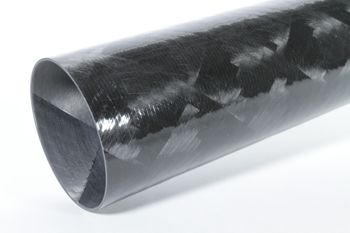
Composite Driveshafts
Carbon Fiber is technology at its finest, usually wound over mandrel fiber soaked with resin. with steel or aluminum weld yokes. Very well suited for circle track and drag racing.
Pros: Very light weight and ultra strong.
Cons: By far and away the most expensive of all driveshafts.
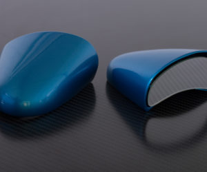
Hybrid Driveshafts
Aluminum with Carbon Fiber Wrap, using any of the aluminum driveshafts with a thin carbon fiber layer over the outside diameter of the tube, plus aluminum weld yokes.
Pros: light weight with extra strength and high critical speed. Price is less than a standard carbon fiber and is still an aluminum shaft.
Cons: Still not cheap.
Keeping those basics in mind, with a little help from your friendly driveshaft shop you can pick the right material that suits your application and budget for your project car. Once the material and measurement criteria are out of the way, you need to know what is critical in the assembly, build and balance of your new custom driveshaft.
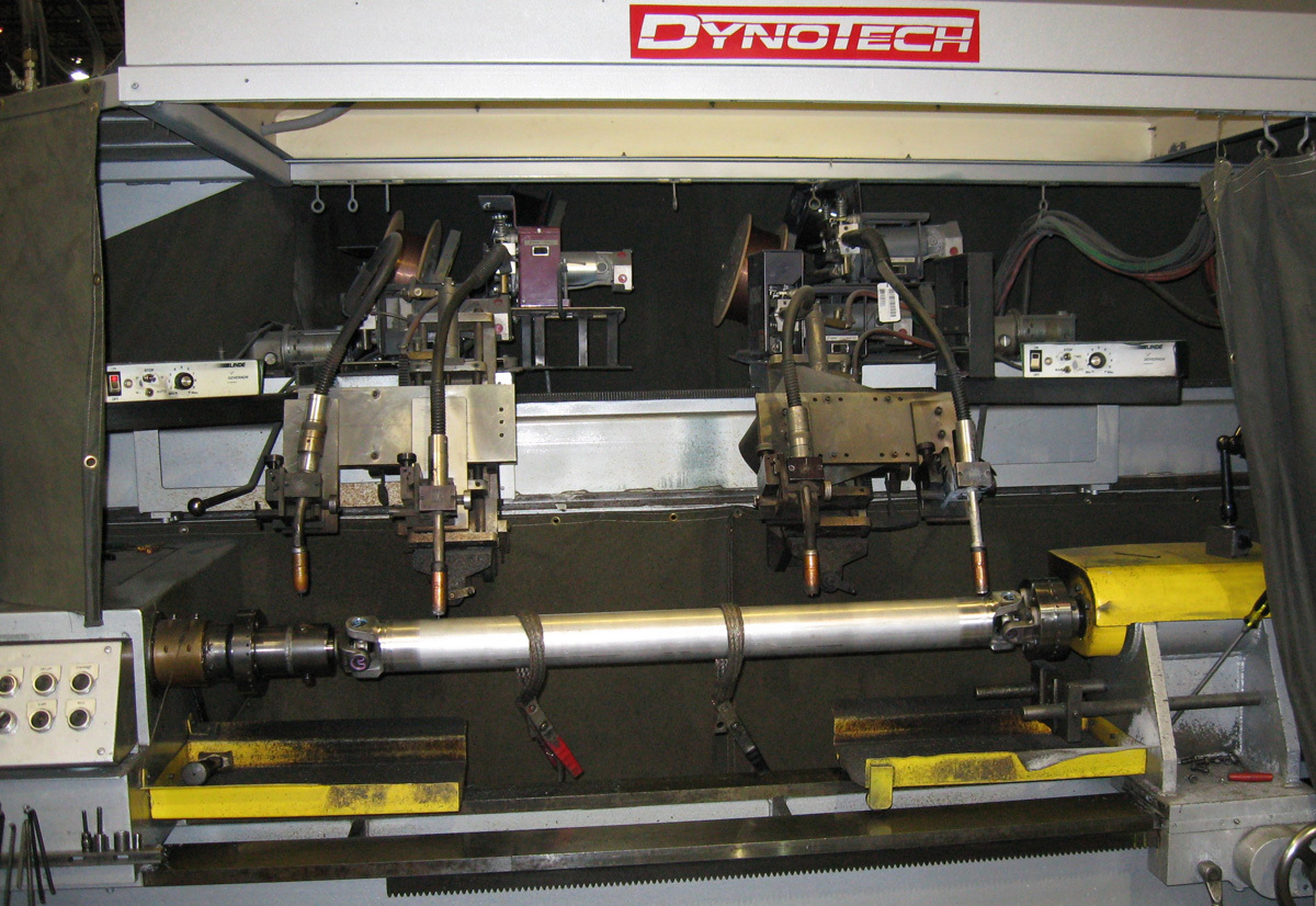
There are several key factors that we use to produce all Dynotech driveshafts: Tube runout, U-joint yoke phasing, U-joint clearance, balance repeatability and balance speed. If you can control each of these factors you are going to end up with a smooth running and reliable driveshaft. What do these terms refer to? Tube Runout is a measurement of how straight your driveshaft is as it rotates about its diametric centerline (axis of rotation). Dynotech suggests that at least three locations be controlled during the build of the driveshaft (both ends and center). Tube runout is a direct contributor to driveshaft balance. If you have high enough runout, your driveshaft will not balance without welding excessive weight on one side. Dynotech keeps all of their tube runouts at 0.020” or less over the entire length of the tube. During both the weld and balance phase of the driveshaft development runouts are checked and minimized
U-Joint Phasing and Clearance can play another significant roll in the build and balance of your driveshaft. During the assembly of your driveshaft you must make sure that the U-joint is centered in the weld and slip yoke. If the U-joint is off center, the entire weight of the driveshaft is rotating off the driveshaft centerline.
In addition, if you do not have your U-joint phasing correct, you will create a fourth-order vibration as a result of the non-constant velocity of the standard U-Joint. (A detailed subject for another article.) U-joint phasing is the alignment of the weld yokes during the build process. The centerline of the U-joint hole on the weld yoke at one end will be in line with the centerline of the U-joint hole on the other end. Dynotech uses specialty fixtures to ensure that the driveshaft is built with less than 0.0025” joint clearance after the U-joint installation and weld yokes are phased to within 0.1 degrees from one end to the other.
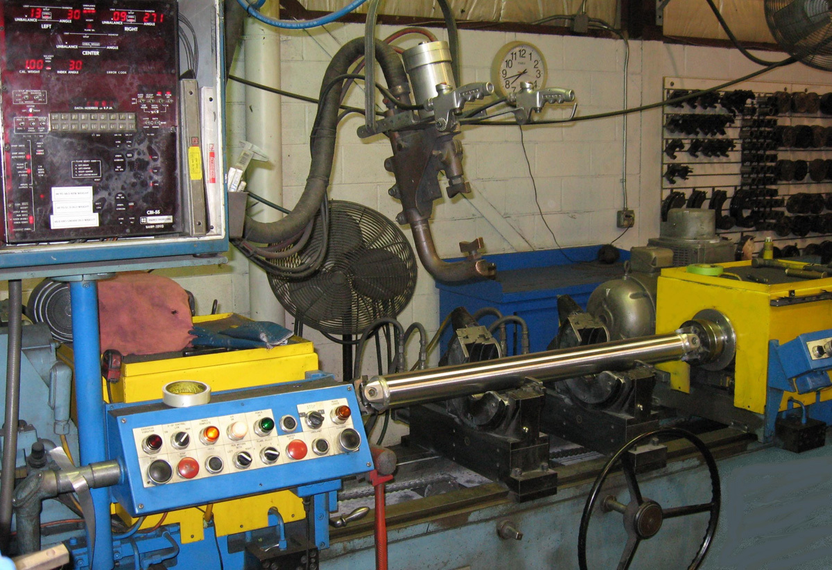
Balance Repeatability and Speed are the final ingredients to what makes a good driveshaft. Dynotech balances all driveshafts to 0.20 oz-inches or less, and expected measurements repeat within ± 0.05 oz-inches. (An ounce-inch is the standard balance measurement unit that relates to imbalance.)
Balance speed is another key element of driveshaft manufacturing. Your driveshaft should be balanced as close to operating speed as possible. Whatever force (imbalance) is generated at 2,000 rpm is increased four-fold at 4,000 rpm, and nine-fold at 6,000 rpm. Even the smallest imbalance force at slow speed can make your car shake at high speed.
U-Joint type: Greasable or lubed-style U-joints have several disadvantages. They are not as strong because the lube channel results in a smaller cross sectional area (less steel to resist the applied torque). Also, they are naturally out of balance. Using a Zerk fitting on the body, plus the added machining for the cross holes, induces a small amount of imbalance. In addition, they are warm forged (a less desirable process for strength). In addition, they require regular maintenance, and the soft seals leak grease at high speed.
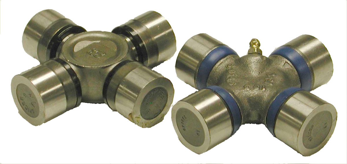
By comparison, solid-body U-joints have several advantages. Because of their solid design and cold forging, they are stronger, making use of the greatest cross sectional area possible. And they are naturally balanced due to the symmetry of the part. They also have a nylon sealing system and are lubed for life by the manufacturer. Expected life is 100,000-plus miles. Because of the seals used they maintain lubrication at any speed.
In technical terms, Critical Speed of a driveshaft is the point where the first-order resonant frequency is excited by the speed of rotation. In simpler words, it’s the point that the driveshaft starts to “jump rope”. It can be reached in any shaft depending on the physical characteristics of the shaft and its speed of rotation. There are several ways to handle the issue of critical speed, such as shaft material, size and design. With something as simple as changing from a steel shaft to a MMC aluminum shaft, you could see as much as a 12-percent increase in critical speed. Items such as balance, balance-weight location and joint clearance all have a direct effect on critical speed.
So what’s the perfect driveshaft if you’re looking at performance characteristics only? You would like it as lightweight and strong as possible.
Why this is so important requires a brief mention of some fundamentals of physics. If you run your car on a chassis dynamometer you will find that peak acceleration takes place at the same time as peak engine torque (because acceleration is defined as force divided by mass). In the case of your car, the mass is constant, so as force increases, so must your acceleration. Therefore the key is more torque.
But not just any torque. The most important torque is at your drive wheels (front or rear). The reason that engine torque and drive wheel torque differ is due to “system loss” or “drivetrain loss”. System loss is the consumption of power needed to rotate the drivetrain including friction and component mass.
So by reducing component mass (driveshaft weight) you consume less power. The less power you use to rotate your drivetrain the more you have to propel your car down the strip or street. Lighter-weight driveshafts give you the best options for reducing “drivetrain loss”.
The second key factor in the ideal driveshaft is critical speed. You want to make sure your driveshaft operates well below its critical speed, or you will experience endless vibration problems and related excessive wear on mating components.
Considering all of the above aspects should help you choose the right driveshaft for your particular project car.


Comments for: SHAFT SCIENCE
comments powered by Disqus