Recalculating a Formula 1
By Steve Temple
Photos by Steve Temple and Courtesy of Joe Scarbo
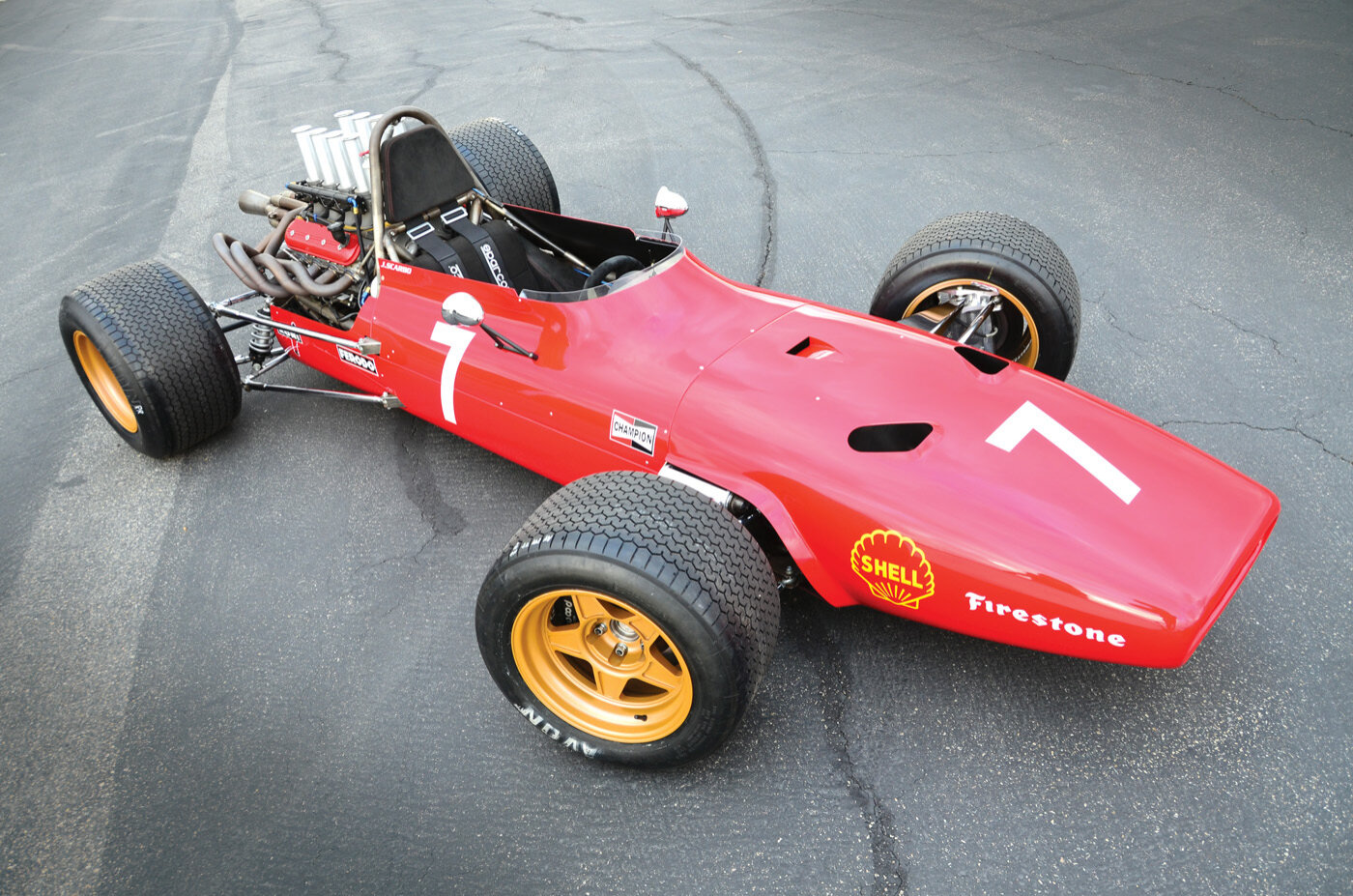
When you have the right tools and expertise, project cars can come together much more quickly. Consider Joe Scarbo’s SVF1, inspired by his passion for Formula 1 cars. A chassis engineer by trade, he uses the latest CAD system to design and analyze his various projects. Tools such as FEA (finite element analysis) help him to run simulations that can make sure a part is strong enough for a particular application before it is ever even built. With these sorts of resources at hand, he was able to complete the SVF1 in less than a year!
By way of background, Joe cut his teeth racing go-karts and building dune buggies, and later did suspension work for Volkswagen’s race programs, but later established his own firm, Scarbo Performance, which develops tube frames and pushrod suspensions for an unusual range of vehicles, everything from a Porsche 911 to a Nissan Titan or Cadillac CTS-V.
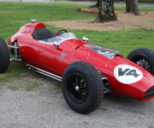
After consulting with some colleagues, he embarked on a whole new venture, drawing on his past chassis and suspension design experience. Why a late-1960s Formula 1 car? “I have been obsessed with this era of F1 since I was a child, and wanted to build a car that was a tribute to all of those cars, and that was practical to own and race.”


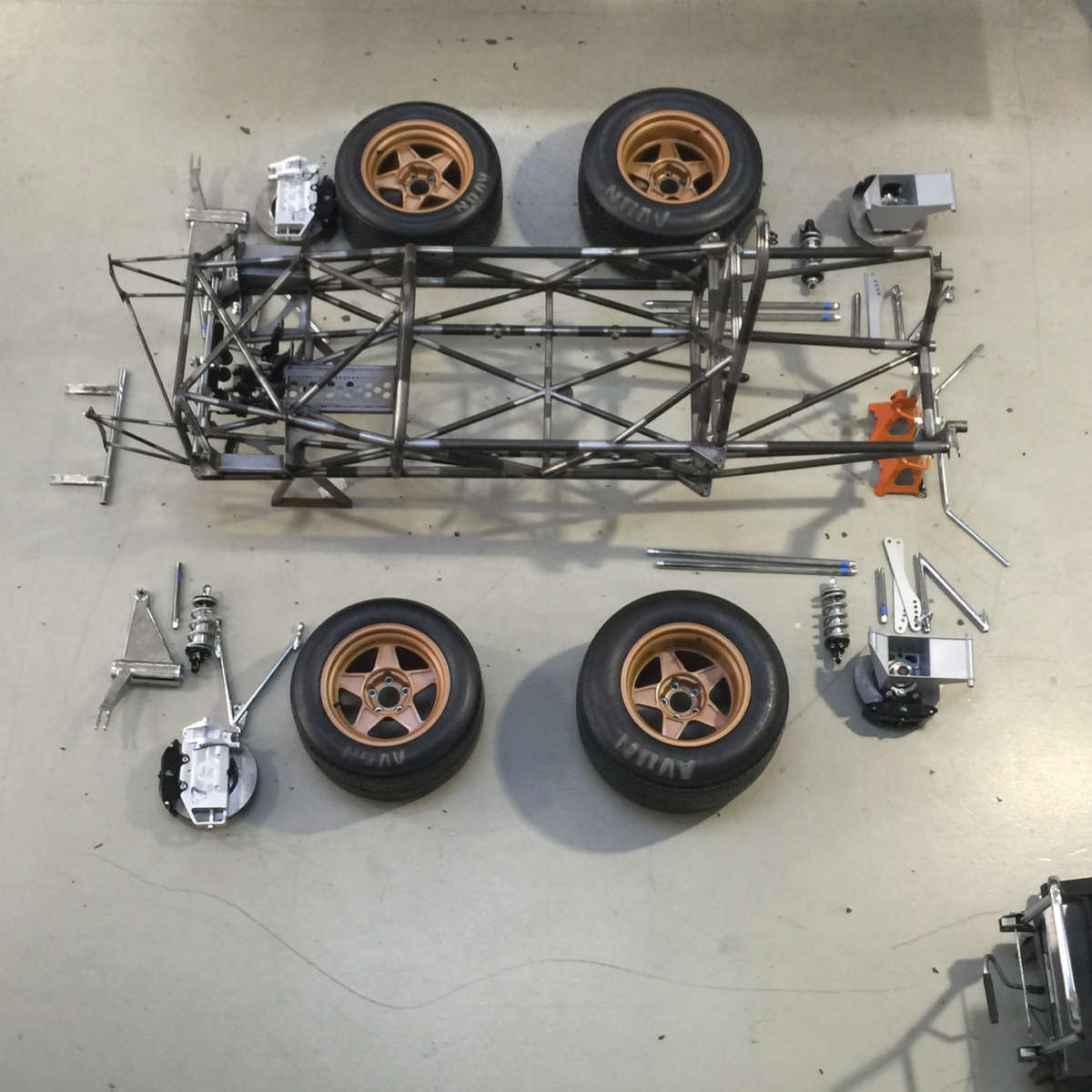
The SVF1 started from the ground up — literally. “I built the car around the wheel package,” he explains. The first design used 17-inch front and 18-inch rear wheels rather than the original 15-inch wheels that were used back in the ’60s. These wheel diameters helped to save cost, not only on the wheels themselves, but also for a set of tires.
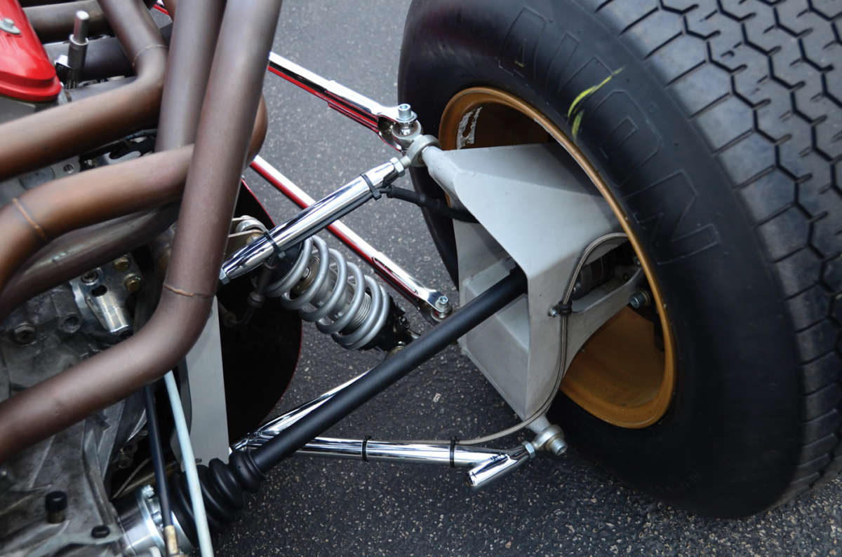
The car was redesigned shortly thereafter to also accommodate authentic-looking 15x12 front and 15x14 rear wheels and Avon race tires. A more costly option, but necessary to closely match the F1 look of the era.
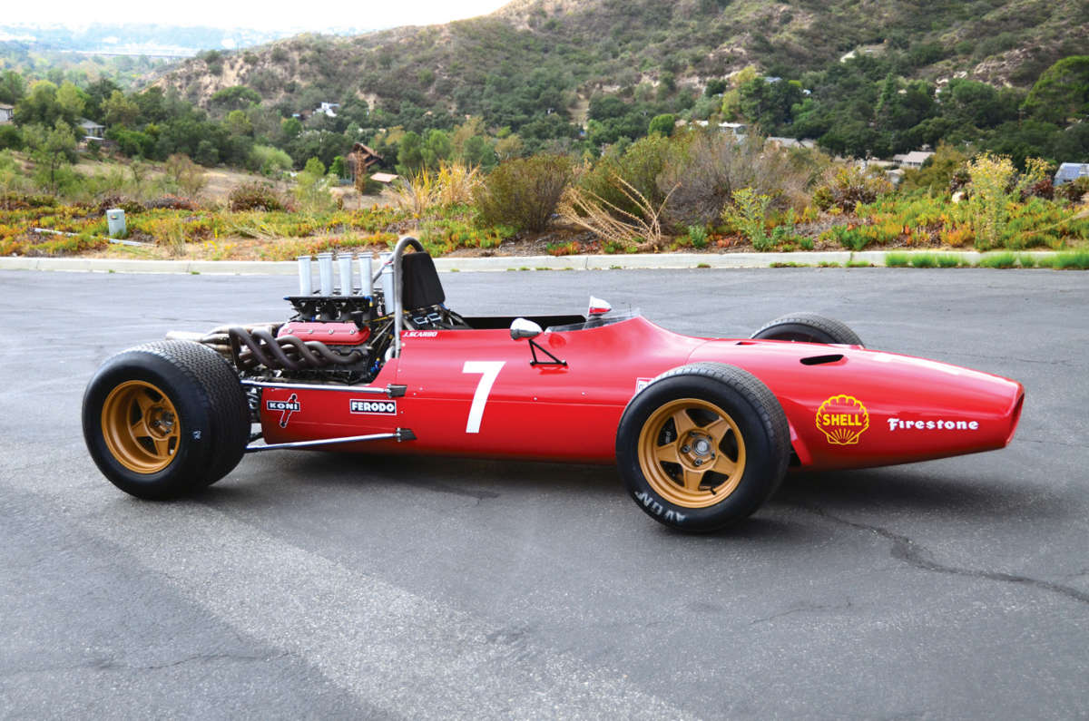
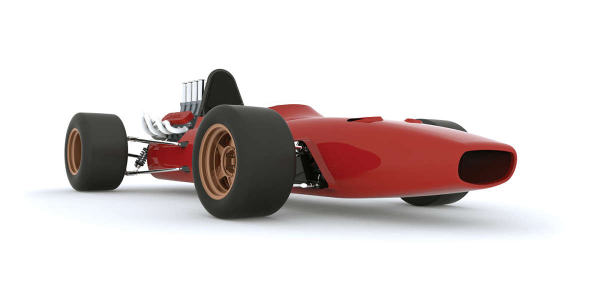
Once the tire and wheel packages were established, Joe used Solidworks 3D software to place them in space, based on original figures for wheelbase and track width. Then, by overlaying an original side-view image, he was able to trace a cross section. This cross section, paired with a front-view image and a series of ovals along the cross section, generated the shape of the body.

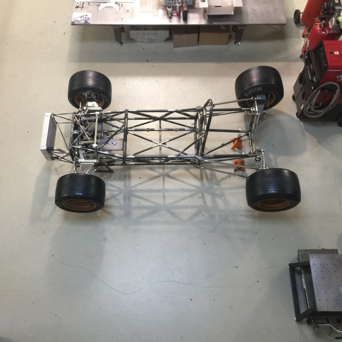
After the shape of the body was established, he designed a tubular steel frame to fit within those boundaries. He adds that this approach allows for checking clearances beforehand, which saves an enormous amount of time and potential need for rework.
As for final fabrication prior to welding, “We design fixtures that mate to the chassis in CAD,” Joe points out. “Then machine the fixture components and place the tubes within the fixtures accordingly. For the bulkheads, which consist of bent tubes, we print out full-scale templates that we can set the tubing on to ensure our bends and cuts are placed accurately.”
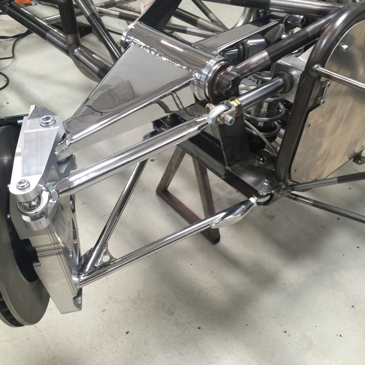
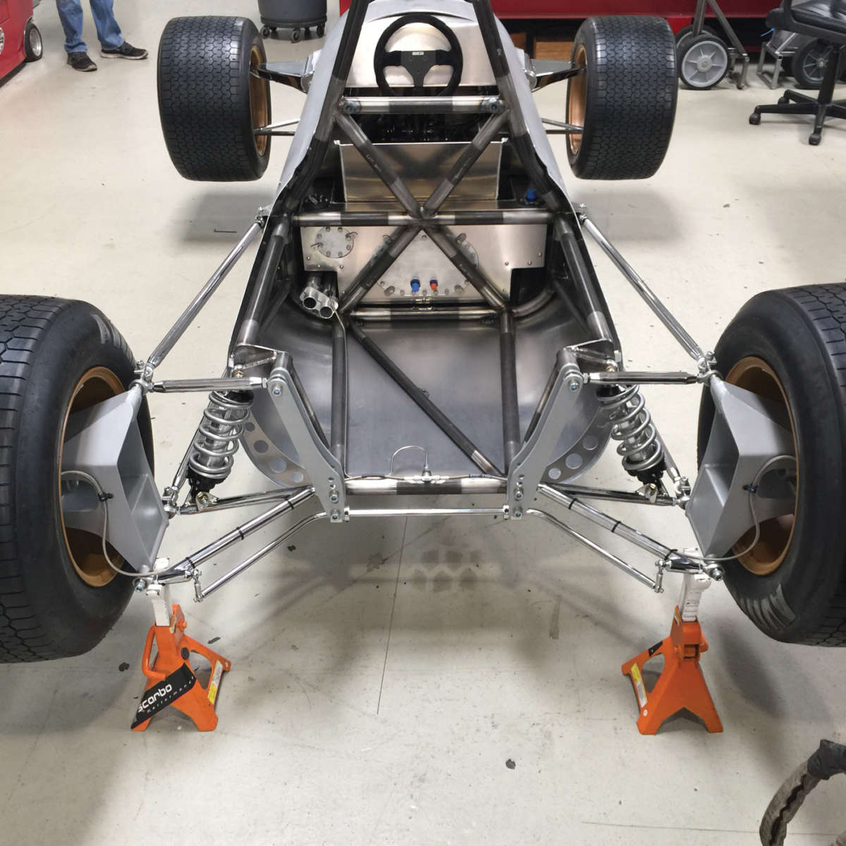

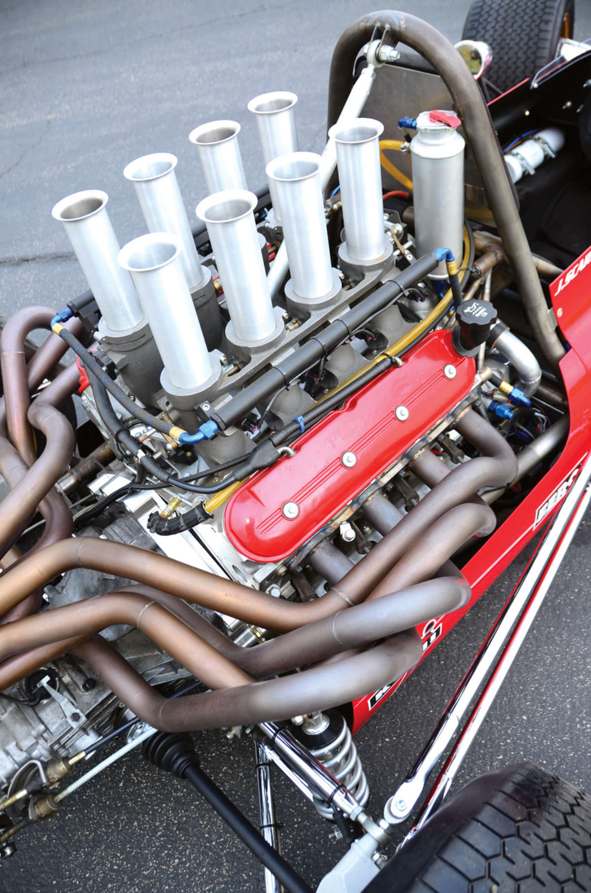
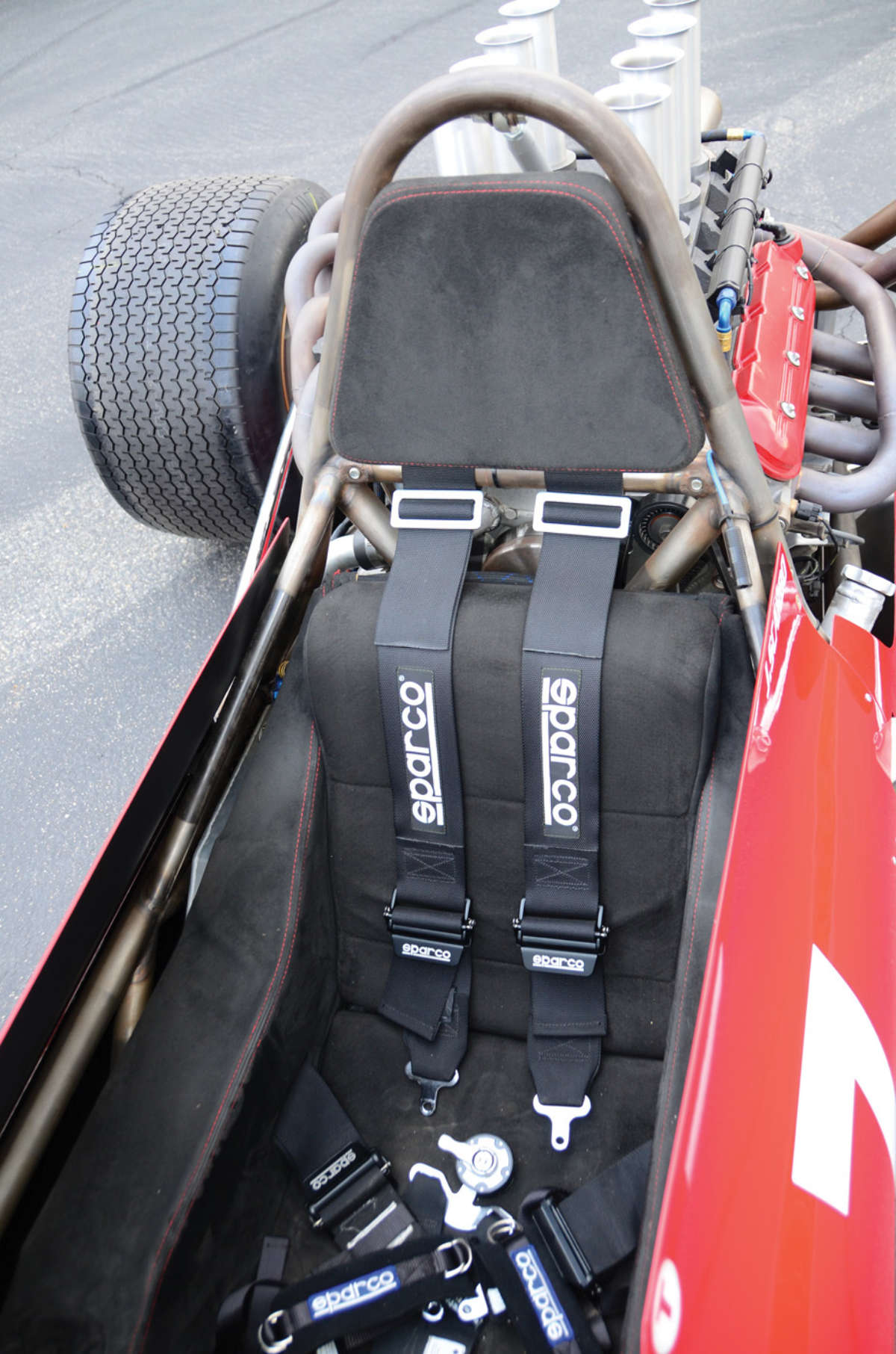
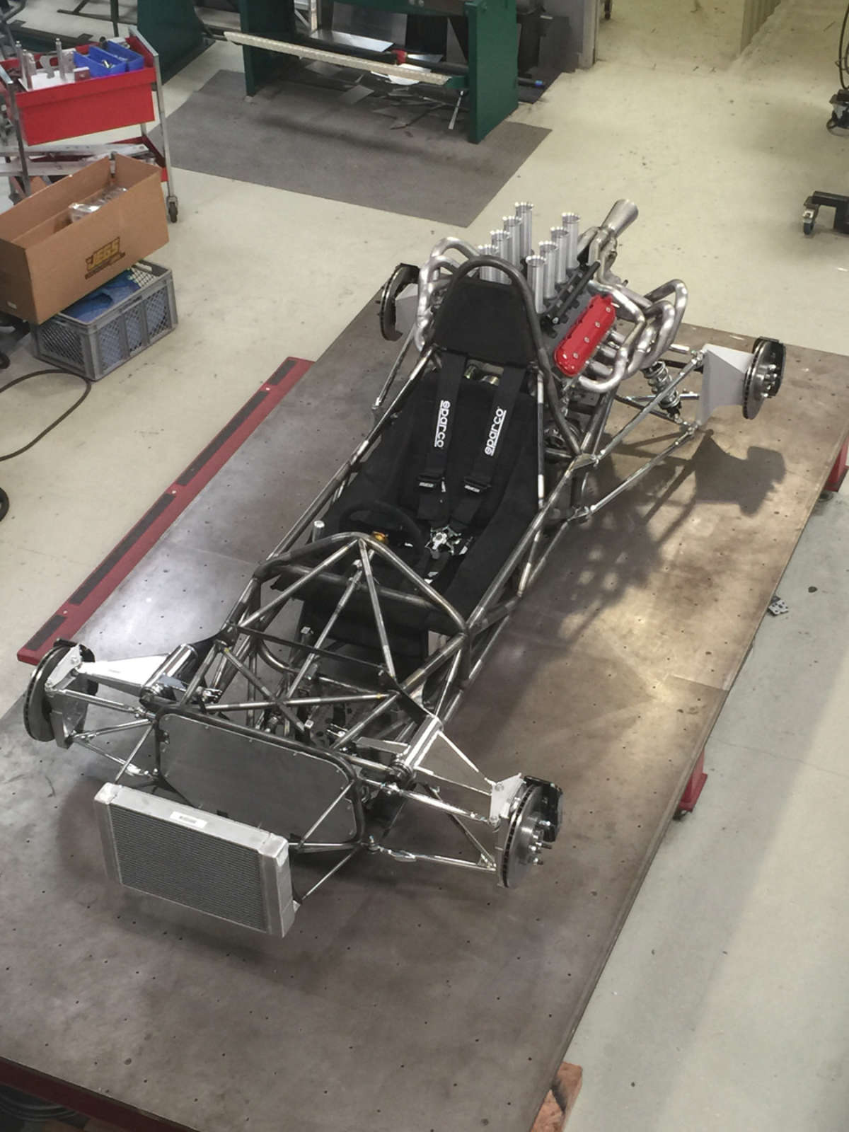
There were some inevitable compromises along the way, such as scaling up the size of the frame by 8 percent, and using mild steel tubing in the base model (the high-performance models are constructed with thinner-wall 4130 alloy steel). He also made the roll hoop much higher than the original F1 cars of the ’60s for safety reasons. In addition, the GM LS3 engine (mated to a Porsche Boxster transaxle) dictated a different type of exhaust system. But he enhanced the performance by slightly raising the roll centers for better cornering grip. Despite these modifications, Joe says the chassis can serve as a platform for several different body styles from the late ’60s, including a Gurney Eagle, Lotus 49, Matra or Ferrari 312.
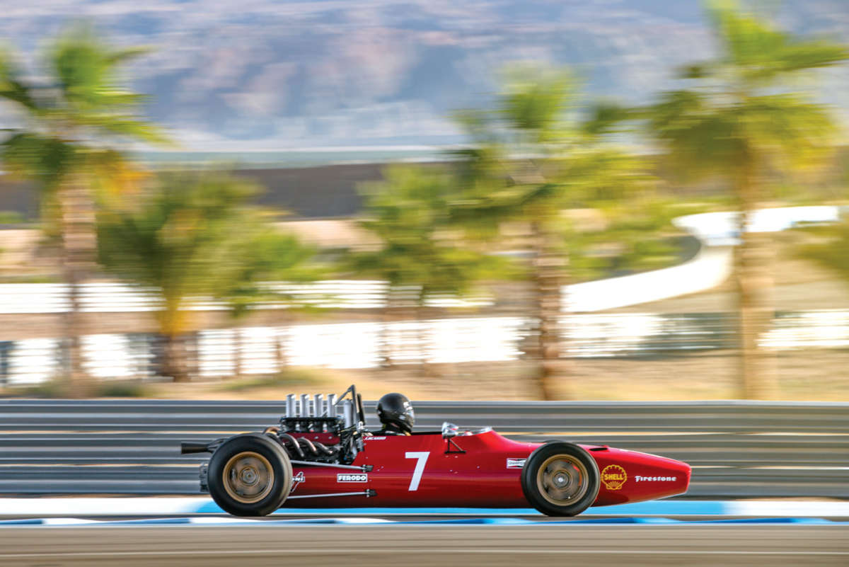
Overall, his design priorities were as follows: “The look, No. 1; the sound, No. 2; and the performance, No. 3,” he says. Even so, the finished car is a solid performer, besting a McLaren P1’s track time at the Thermal Club by a half-second!


Comments for: Recalculating a Formula 1
comments powered by Disqus